
PHOTOVOLTAIC SOLAR COOKING
WITHOUT BATTERIES
WITH PTC CERAMIC HEATERS

General summary of the documentation:
- Home
- Presentation of the cooker
- Design of the cooker
- 1 - Building and using a cooker
- 2 - Building a cooker: appendices
- 3 - Theoretical presentations
- 4 - Technical information
- 5 - Photovoltaic panel supports
- 6 - Automation of PTC ceramics
- 7 - Photovoltaic solar water heater
- 8 - Library
- Who are we?
the parts shown in grey are still under construction.
Part 5 ORIENTABLE SUPPORTS
FOR PHOTOVOLTAIC SOLAR PANELS

- Chap 1 Preliminaries
- Chap 2 A support at ground level
- Chap 3 A support on a small post
You can click on most of the diagrams to enlarge them as required.


, general view
Chapter 1 Preliminaries
- 1A) Why a directional panel ?
- 1B) The main enemy is the wind
- 1C) A panel and its support must never be warped
- 1D) Handling and storage: always upright
The aim is to install a photovoltaic panel on a adjustable support,
so that you can work from sunrise to sunset, and to improve the
yield of a panel that can be pointed in azimuth (East-West) and
height (from the horizontal to the zenith).
The installation is specifically designed for home solar cooking.
Let's take a cooking session lasting two hours, from 10am to 12pm.
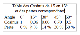
In one hour, the sun travels 15° from east to west (360° in 24 hours). When the collector is
not perfectly pointed towards the sun, there is a certain loss due to the "
cosine effect". When the offset is 15°, the loss is 4%.
If the user anticipates a little, and points the collector"towards 11 o'clock" from the start of
cooking, the loss will be 4% at 10 o'clock, zero at 11 o'clock, and 4% at 12 o'clock,
on average less than 2%. In the case of food cooking, this is negligible and
unmeasurable - and without having to change the orientation of the collector.
That's four hours' cooking time, between 10 a.m. and 2 p.m. If, at the start of the session,
the user tunes the collector to "11 o'clock", followed by an intermediate adjustment at 1
o'clock, the loss will also be less than 2%, at the cost of a single intermediate
adjustment over the course of a 4-hour session.
 And it will then be possible to repeat, under the same conditions, another firing from 14 to 16 or 18 hours. By combining the use of an adjustable panel with the use of a cooker with PTC resistors whose temperature level allows the cooking vessel to be insulated, the overall efficiency of the installation is further improved.
"Yields are multiplicative (and so are losses...)".
The storage battery and its accessories lose much of their interest: it's an additional gain, both financially and ecologically.
By installing the panel on a post, it is possible to avoid the effects of shadows at ground level, but then its main enemy is the wind, hence the need to over-size the installation somewhat. 80% of the materials will only be used for a few per cent of the time, during a very strong gust of wind. In the event of a storm, the collector should be placed in a vertical position, pointing in the direction of the wind.
Solar collectors are designed to have a long service life, which is one of the requirements of banks: banks agree to finance photovoltaic farms or power plants on condition that the panels have a service life longer than the term of the loans they provide...
If you want to keep a panel for many years, there are a number of precautions you must take, otherwise solar photovoltaics will only bring disappointment. And if the panel was bought on credit, it would be a shame to break it before the loan is repaid...
The main enemy of solar panels is the wind.
You shouldn't say "the wind blew the panel away" but "the panel wasn't installed properly" or "the ballast on the support wasn't sufficient" or "the panel wasn't sheltered despite the storm that was threatening".
The figure to be taken into account for the wind uplift resistance of a structure is 100 kg per m² . This figure is valid for sheds, roofs, etc., and is even more valid for collectors that can take the wind on both their front and rear faces.
For a fixed 1.5 m² collector, the fixings, anchors, plugs or other devices must therefore withstand a total pull of 150 kg. In the case of a ground-mounted collector that has to be moved once every two hours or so, it is not possible to leave 150 kg of ballast permanently.
A solution is to make up the ballast with bags of sand or gravel weighing around a dozen kilograms, which are easy to place on the base of the support. And when the wind becomes too threatening, you can easily remove the panel and store it under cover.
The collector is covered by a glass plate.
It can therefore never be "twisted" or "warped", and its surface must always be flat.
A plane is defined by two parallel straight lines, for example the two aluminium angles on the long sides of the collector. With a minimum of practice, you can check at a glance whether they are parallel or not: the observer bends down as far as necessary to place his eye on the same plane as the glass surface of the collector, and observes, 'straightening' the two angles.
This is exactly the same operation as that of the carpenter who 'visually' aligns a row of posts. Here we're not talking about posts, but the two long angles of the panel. If they are at an angle to each other, then the surface glass is in a bad position.
A plane is also defined by a straight line and a point. In the adjustablex panel systems shown below, the straight line is represented by the alignment of the two axes of rotation, and the point is represented by the height adjustment fixture. During orientation operations to follow the sun, the panel remains wedged on its cradle and rests on a straight line and a point, so there is no great risk. If the support is placed on the ground, it is the base, dragged along a more or less flat surface, which will deform somewhat, but without transmitting its deformation to the mobile cradle.
It is during handling operations, for example to move the panel to a safe place in the event of a gust of wind, that there are the greatest risks: the two operators must fully understand the concept of flatness, and carry out all handling operations symmetrically in relation to each other.
The penalty for non-compliance with the flatness rules is fairly simple: a crack of varying length, running diagonally across the panel glass.
In terms of their mechanical strength, collectors are designed to be installed and then not to move throughout their lifetime, and it is the underlying rigid infrastructure (framework of the house, shed, etc.) that ensures that the panel is flat. During handling or transport, the panels are usually resting on a pallet, which performs the same function.
In our case, the panel will be handled several times a day. It is therefore essential that it rests on a non-deformable support.
Chapter 2 A support at ground level
- 2A) Supplies and miscellaneous information
- 2B) The baseplate
- 2C) The adjustable cradle
- 2D) Other elements of the collector support
A multitude of adjustable supports and variants can be designed.
Here we have chosen a wooden support for a panel measuring 991 mm x 1645 mm high and 280 Watt-peak, which can be adapted as required. It comprises
A - a base, resting on the ground
B - an adjustable cradle for the collector
C - a telescopic support to orient the cradle according to the path of the sun in the sky

without its panel
1 : uprights
2 : crosspieces
3: hinge
To orientate the collector according to the path of the sun from East to West, the assembly is simply dragged along the ground, pulled by a cord or a metal hook.
Wood supplies
Wood does not need to be planed; it should be protected with woodstain or, failing that, paint. The proposed plans have been drawn up for a wood section of 100 x 40 mm. Other cross-sections can be adapted.
- Base: two 1.955 m uprights for a 1.65 m panel; three crosspieces, length of crosspieces = exact width of panel, plus 5 mm, i.e. here 0.991 + 0.005 = 0.996 m
- Cradle: two 1.84 m uprights, and three 996 mm crosspieces.
- Diagonals: two 1.55 m lengths. For the diagonals, a 50 x 40 mm section would suffice.
Supply of bolts and hardware
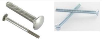
- M8 x 100 mm Japy round-head square-neck "TRCC" bolts; alternatively, threaded rods with wide washers can be used.
- M6 x 100 countersunk-head bolts, for example from vis-express.fr Reference: 3101610002, or better still in stainless steel 8301610018, given the smaller diameter.
- Cross-head countersunk wood screws Ø 4.5 mm partial thread, length 70 or 80 mm, vis-express.fr ref. 2008457002 or ref 2008458002 ; or: leroymerlin.fr Ø 4 mm L 70 mm Réf 66931732
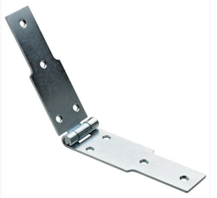
- Fillet hinges, length 300 mm (when opened flat), width 50 mm (this is the length of the hinge pin). Per example: leroy-merlin Ref 67555180
- Drill bits for bolts and wood screws
- Stain or paint .
The worktop
Its first quality is to be... flat, in the sense defined above; if it is also level, it is all the easier to drill holes perpendicular to the surface of the wood.
The work surface can be on a large table, or trestles, or on the floor, but it must be stable and shimmed as much as necessary to ensure good flatness, which is checked using the procedure described above for the panel.
Drilling perpendicular to the work surface When drilling with a hand-held or electric drill, it is necessary to have a helper, or better still, two helpers at 90° to check that the drill is perpendicular to the work surface.
Assembly in two stages
Almost all the assembly is carried out in two stages: firstly, assembly using wood screws, with one screw for each joint, then final assembly using bolts.To make wood screws easier to use, drill the first piece of wood to the "outside thread" diameter of the screw; PZ No. 2 bit; if necessary, coat the thread with a little tallow or other grease.
To reduce the risk of the countersunk head of the screw splintering the wood, it is advisable to countersink the hole or, better still, use washers for countersunk-head screws.
Once the assembly with the wood screws has been completed and checked, always install at least two bolts per connection between two pieces of wood.
2B) The baseplate
General assembly of the baseplate
- On the two uprights, draw lines at 100 and 1365 mm.
- Screw on the intermediate crossbar and the front crossbar.
- Fit the two shims, measuring 180 x 40 x 100 mm.
- Make the squares. Here, for example, the length of the diagonal between the lines is 1632.8 mm.The assembly is square when two cross diagonals are the same length.
- install a temporary diagonal .The wooden diagonal will be installed later on the underside of the base.

Installing the hinges
 Preparing the hinges
- Remove the pin by filing off the riveted head, then hammering it out. This pin must be removed when the panel is stored. The original pin has a diameter of 7 mm, and can be replaced by a piece of Ø 6 mm rebar, or even by a Ø 6 mm bolt (not very elegant), or by any other means.
Let's agree that the half-hinge with two axle supports will be installed on the baseplate, and that the half-hinge with a single axle support will be installed on the cradle.
- enlarge the end hole of the baseplate half-hinge to Ø 8.5 mm (to be on the safe side when enlarging the hole, fasten the half-hinge with screws to a larger piece of wood to hold it firmly in place).
- check that the other holes in the hinge allow an M6 countersunk head screw to pass through. Check that the countersunk holes match the screw heads.

Position the half-hinges on the baseplate
- Draw a square line on the two spacers at 1 330 from the intermediate crosspiece.
- Draw the two axes of symmetry in the middle of the shims. In our case, the distance between the axes of symmetry is 896 mm; this may vary depending on the cross-sections of the wood used, the important thing being of course that this centre-to-centre distance corresponds later to the centre-to-centre distance of the hinges on the adjustable cradle.
- complete the layout of the half-hinges.

on the baseplate
and fix the hinge halves
with an M8 Japy TRCC screw, and with M6 countersunk screws.
As a precaution, only one half-hinge can be fixed, the other being positioned later "by presentation" once the cradle has been completed.
Turn the baseplate over
- install the final diagonal
- Install the rear crossbar
- install the skates
The skates are wear parts installed under the baseplate, two under the front crosspieces, and one under the rear crosspiece, dimensions ≈ 150 x 100 x 40.
Under the front crosspiece we end up assembling three layers of wood.Japy M8 x 150 and M8 x 130 bolts are available (vis-express.fr 8414811518). You may prefer to use M8 threaded rods. Under the skate, countersink the nuts or bolt heads to diameter 22 or 24 using a flat bit.
To reduce the thickness of the bolts, the skates can be shifted slightly inwards, but this is not very satisfactory. They can also be shifted outwards, provided that a longer crosspiece is used.

2C) The adjustable cradle
Assembling the cradle
The cradle is assembled "upside down", so that the hinges can be positioned correctly.
Present the two uprights, then the bottom crossbar below, and the intermediate crossbar above. Block under the stile in line with the intermediate rail, to make it easier to work. Draw a line 100 mm from the foot of the jamb, then 1250 mm. Using a square, mark the flat and the edge of the upright.

to install the half-hinges
- Screw on the intermediate crossbar, checking the 996 mm "outside jamb" dimension.
- Install the bottom crossbar, positioning the wood-screw in the middle of the assembly. Countersink the hole to embed the screw head, which will later be covered by the fillet hinge.
Dimensions of the diagonal
Below are the dimensions for the diagonal, for a 50 mm wide diagonal on the one hand, and a 100 mm wide diagonal on the other.Both solutions are good, depending on the wood available and its quality.
Indicative dimensions are also provided for the location of the assembly screws and bolts.

for screws and bolts
Squaring the cradle and installing the diagonal
As with the base, the cradle is squared by measuring crossed diagonals, which must be equal. Here, for example, the measurement is 1598.3 mm. If necessary, rectify the squareness with a hammer.
Check that there is a free area of 200 mm at the bottom for installing the half-hinges, and fix the diagonal.

If you need to remove any apprehension, you can turn the cradle upside down and place the collector on it (taking all necessary precautions!) to check that the long sides of the collector remain within the 5 mm of clearance initially provided. Then... turn the cradle upside down again.
Installing the diagonal The half-hinges of the cradle
On the two half-hinges, enlarge one hole to 8.5 mm diameter, and check that the other holes will accept the head of a countersunk M6 screw.

Positioning the two half-hinges :
- draw a line with a square 80 mm from the previous line
- trace the two axes and the two lines 25 mm apart
- and bolt the two half-hinges
As a precaution, embed the nut of the small M6 x 60 bolt in the upright, so as not to interfere with the baseplate/cradle closure.
- With the cradle still upside down, install the top crossbar.

on the cradle
Assembling the baseplate and cradle
With the baseplate horizontal on the floor, present the cradle vertically, assemble one of the hinges with its pin, and position the other half-hinge on the baseplate.
2D) Other components
The telescopic adjustment tube
There are many possible solutions. A metal tube version is shown below, but it could very well be a reconstituted wooden tube (two cleats clamped between two strips of plywood), or a mixed solution with a wooden tube and metal runners.
In order to have a sufficient range of adjustments, it is necessary to provide two or three central sections section 25 * 25 * 2mm of different lengths (A), and two end slides section 20 * 20 * 2, drilled every 60 mm (B).
Ø 6 mm pins work very well.
Drill to a much larger diameter than the pin, to make adjustment easier.
When the sun rises very high in the sky, it may be preferable to install the tube on the end crosspieces instead of on the intermediate crosspieces.

Collector mounting brackets
These are used to hold the collector on its cradle (be careful of the wind...). They should be made, for example, from a strip of flat iron or aluminium, section 30x3 mm, and fixed with screws of at least 4 x40 mm.
Pre-drill the wood to the diameter of the screw body, and preferably use A2 stainless steel lag screws.

Weights and their support
Ten kg bags of gravel are a good choice. Allow a dozen bags. When the collector is not in use, particularly at night, spread the bags out on boards placed on the base. When the collector is in use, remove the weights to make it easier to drag the collector along the ground. If you're worried about a gust of wind during the day, you can also tie the upper crosspiece of the cradle to a tree.
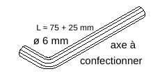
An adjustment indicator
This is a rod positioned perpendicular to the surface of the collector. The length of the shadow cast by the rod indicates how well the collector is pointing.
- 8 mm plywood plate
- rod (the gnomon) made from a Ø 10 mm bolt L = 120 mm, the hexagonal head of which has been cut off
- to make it easier to read the shadow, install a white PVC sheet; here: a round cover.
The small cleat holds the plate securely against the upright.
The whole assembly is screwed under one of the cradle uprights.

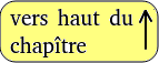
A Ø 8mm rebar hook
This is used to move the baseplate on the ground.

the baseplate on the ground
Two imperative instructions to be given to the user
1-During hours of use: The collector may only be moved on the ground by pulling the baseplate using a cord or hook. It is strictly forbidden to push or pull on the mobile cradle to avoid any dangerous deformation of the collector. For the same reason, when adjusting the height of the cradle, it should only be gripped by the middle of the upper crosspiece and not by its ends.
2-If the collector is not to be used for a long time, or in the event of a storm, store it in a safe place, with its cradle, handled vertically and stored on its lower crosspiece.

Chapter 3 A support on a small post
- 3A) Preparing the cradle parts
- 3B) Assembling the cradle parts
- 3C) The tubular post
- 3D) Summary of supplies
- 3E) Towards a support on a large post?
We're talking about a 375 Watt peak photovoltaic panel, dimensions 1755 x 1040 mm, weight 27 Kg. The support can be adapted to any panel size. The post itself is made of metal tubing.
In the previous case of the panel support resting on the ground, the rigidity of the cradle receiving the panel was ensured by bolted rectangular-section uprights and crosspieces. In the case that interests us here, the principle is different: the uprights and crosspieces are square-section rafters, and the rigidity of the assembly is ensured by thick plywood panels - a thickness that must be respected when sourcing materials.
The cross-sections of the wooden rafters are not imperative; you simply have to adapt.

The foot of the post is embedded in a slab, or in a small mass of concrete buried in the ground. The height of the photovoltaic panel is adjusted using a cord attached to the orientation lever.

3A) Preparing the cradle parts
Left and right uprights
6.2 or 6.0 mm diameter holes for Japy M6 x 120 bolts
If drilling with a portable drill, ask one or two helpers, positioned at 90° to each other, to check the verticality of the drill.
 If the length of the drill bit on the pillar drill does not allow the hole to be drilled completely, the drilling can be completed at a later date using a twist drill bit fitted to a hand-held drill.
Observe the profile of the aluminium frame of the photovoltaic panel, and check that it will not encroach on the domed heads of the bolts; if necessary, slightly offset the row of holes, or carry out a countersink before drilling with an 18 mm flat drill bit, 4 mm deep, to countersink the bolt head.

Top and bottom crosspieces

Plywood
18 or 21 mm plywood, CTB-X "exterior" quality; cuts must be perfectly square; 6 or 6.5 mm diameter holes. Some holes will be drilled during assembly.


Drill diameters 50 using a hole saw.

and panel retainers
3B) Assembling the cradle
Protect the wood: linseed oil with turpentine, or hot linseed oil (without turpentine!), woodstain, etc.
Wind is the main enemy of the photovoltaic panel, which must always remain flat - otherwise it will crack diagonally. If the panel is installed on a roof, the framework under the roof will ensure that it remains flat. In the case of post installation, the panel support is responsible for keeping the panel flat.
- Install on a flat work surface:
the support must be built on a perfectly flat surface, and if possible level. For example: on two planks installed on four trestles, making sure that the two planks are on the same plane and that they are level. This is done by eye, bending down to the level of the two planks to check that they are parallel in height.
- You will need some heavy-duty carpenter's screw clamps.
- The squareness is checked using the "3/4/5" method, or by checking that the diagonals are equal.
There are several assembly methods to choose from.
The first method of assembly :
Overhead rafters
When the assembly is square, hold it together with clamps, complete the drilling and start installing the bolts.
Japy bolts, round head, square collar, M6 x 120, A2 stainless steel, available from visexpress. fr, ref 8414612018_1. Alternatively, you can use galvanised bolts, ref 4515612002_1, but after several years dismantling is not certain - except perhaps to grease the threads before use.
Large washers with an external diameter of 18 mm, e.g. vis-express.fr, ref 8534000618_1 Nuts ref 8425000618.
Assemble the main stiffener, the two gusset plates and the crosspieces. NB for the top crosspiece, complete the two holes in the middle, but do not bolt them; they will be used to receive the operating cord for adjusting the height of the cradle. They should even be enlarged to 10 or 12 mm in diameter.
Install the four axle brackets, inserting the tubular axle to ensure correct alignment. Position the axle between 3/5ths and 2/3 of the length of the panel, starting from the bottom. You can always move them if you are not satisfied...
Finish by installing the two retainers at the bottom of the panel.
A second assembly method :
plywood on top
Initially, the panel is assembled using wood screws. The drilling and bolting are then completed after turning over. Pre-drill the plywood to the diameter of the screw body, and countersink the holes. Use partially threaded stainless steel wood screws, for example 4.5 x 60 from vis-express.fr, ref 8703456018_1, or 4 x 60. Grease the thread before screwing into the wood. Ordinary dichromate screws can be used, but subsequent dismantling will be impossible due to corrosion.

Fixing the photovoltaic panel
to its support
The panel is held in place by aluminium lugs made from 30 x 2 mm flat aluminium profile, bolted to the panel's aluminium profile and secured to the wooden rafters by lag bolts.
Nuts and bolts for fixing the lugs to the panel: A2 M5*15 stainless steel bolts, for example vis-express.fr ref 8722501718 or 8412501618; washers ref 8533000518_1; nuts ref 8425000618_1.
 After installing the panel on its frame, and fixing the lugs to the aluminium frame, drill a hole in the wooden frame to accept the 5*40mm lag bolts ref 8400504018_1.
- drill a 40 mm hole according to the diameter of the screw body (3 mm?)
- drill to diameter 4.5 mm along the length of the unthreaded part
To adjust the drilling depth, slip a small tube of the appropriate length over the drill bit. Use only stainless steel screws and grease the threads, even on wood (tallow works very well).

fixing the panel to its support
3C) The tubular post

Metal tubes
Supply tube, galvanised if possible.
- External diameter 48.3mm tube, known as "40*49", 3.00 m long.
A length of 1.08 m for the horizontal axis
A length of 1.40 m for the upper part of the post, to be inserted in the lower part.
A length of 0.50 m, for the east-west orientation lever.
- Tube with an external diameter of 60.3 mm, known as "50 x 60", 1.00 m long, for the lower part of the post, embedded in the concrete of the base.
Supply: e.g. lemetal.fr, ref 10337 and 10339 (not galvanised).
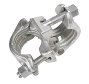
Supply of the collar
Fixed 40*49 scaffolding collars (orthogonal, not oriental) e.g. echafequipement.com ref "Collar orthogonal 49 x 49 mm".
If the installation appears to be undersized for local conditions, tubes and collars of a larger size can be used.
 Assembling the pipes
The top clamp is clamped in the middle of the horizontal axle; the axle is rotated 'up and down' on the plywood axle supports. This upper collar is also clamped at the head of the 40 x 49 tube in the upper part of the post.
The lower collar is clamped to the tube in the upper part of the post, approximately 50 cm from the top end.
The upper part of the post, made of '40 x 49' tube, therefore slides about 1 metre inside the lower part of the post, which is made of '50 x 60' tube.
During East-West rotation, there is therefore a strong gap between the underside of the collar and the upper end of the '50 x 60'.The device can be improved by cutting a length of 5 or 6 cm from the 60.3 tube and installing it under the collar, which will be more satisfactory.
N.B. To draw a square cut on a tube, wrap a sheet of paper tightly around the tube, edge to edge.
East-west orientation lever
Install a threaded rod (with adhesive tape) or similar horizontally at the end of the operating lever to secure the panel adjustment cord.A 6 or 8 mm diameter braided cord would be suitable.
The other end of the adjustment lever should not protrude too far from the collar, so as not to come into contact with the surface of the photovoltaic panel when it is in the "storm" position.
To limit water ingress into the 50*60 tube, make a small skirt around the 40*49 tube above the lower collar. Note that the '40 x49' tube slides into the '50 x 60' tube up to the level of the concrete ballast, which reduces the overall strength of the support in the event of a .
Storm' position
Position the panel vertically, and orient it across the wind. Tie the bottom rail very firmly to the '50 x 60' tube to avoid vibrations.
Concrete ballast
The dimensions suggested are a minimum, and may need to be adapted to suit local conditions. Reinforce the concrete with 2 or 3 mild 6 or 8-twist iron frames or hoops positioned around the foot of the tube to prevent the concrete bursting as a result of the leverage effect of the tube.
The concrete ballast can also be replaced by a device with a mobile ballast (sandbags, stones, etc.). This would make it possible to move the photovoltaic collector, for example, to find a better location for it, or, if it is unsuitable, to send it elsewhere.
3D) Summary of supplies
(not exhaustive)
Wood and plywood
Rafters 75 x 633, length 3.00 metres, 2 units
18 mm CTB-X plywood, 1.00 m².
(NB the flanges for holding the axle are missing)

Galvanised steel tube
diam 40*49: 3.00 metres
diam 50*60: 1.00 metre
Tools and hardware
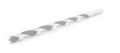
Spiral wood bit
Linseed oil, turpentine / Woodstain
Grease, tallow
Scaffolding clamps
Aluminium flat profile 30 * 2 * 1000 mm
Nuts and bolts
Japy TRCC bolts 6*120
Large washers M6 * 18
Nuts M6 A2
PZ2 stainless steel screws 4.5 x 60
M5 * 15mm stainless steel bolts; washers, nuts
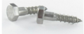
Lag screw 5 * 40mm
Concrete 100 litres (235 Kg)

3E) Towards a support on a large post?
Depending on the effects of shade on the site, you may wish to install the panel higher up, for example on top of a wooden post.
The post can be embedded in the ground, or guyed.
At the top of the post and approximately 1.50 metres from the ground, install two vertical sections of '50 x 60' tubing 30 to 40 cm long, secured to the post with clamps. Place a slightly shaped hardwood wedge between the post and the tube.
A '40 x 49' tube slides through the two sections, and you end up with the previous example of a support on a small post.
Band-it stainless steel clamps: see for example
esska.co.uk/shop/Colliers-de-serrage/BAND-IT--27610