
PHOTOVOLTAIC SOLAR COOKING
WITHOUT BATTERIES
WITH PTC CERAMIC HEATERS

General summary of the documentation:
- Home
- Presentation of the cooker
- Design of the cooker
- 1 - Building and using a cooker
- 2 - Building a cooker: appendices
- 3 - Theoretical presentations
- 4 - Technical information
- 5 - Photovoltaic panel supports
- 6 - Automation of PTC ceramics
- 7 - Photovoltaic solar water heater
- 8 - Library
- Who are we?
the parts shown in grey are still under construction.
Chap 1 PTC ceramic resistors
- 1A) PTC ceramics: overview
- 1B) Resistance and electricity: a few reminders
- 1C) The ceramics used in the cooker
et leur approvisionnement
1A) PTC ceramics: overview
The use of ceramic resistors, and the resulting consequences, are the main
specificity of the electro-solar cooker proposed here. The heating elements
in the cooker are not conventional heating elements like those in a toaster
or an iron, or glass-ceramic or induction-type devices, but ceramic
heating elements.
Ceramic resistors are components whose electrical resistance varies
significantly according to their temperature. TDK / EPCOS, a subsidiary
of Siemens and Matsuhita specialising in the manufacture of passive
electronic components, has published extensive documentation
on PTC ceramics, available here.
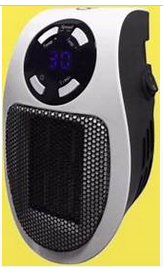
One example among many: the small 'ceramic space heaters' available in all the heating/household electrical departments of supermarkets, to be plugged directly into a wall socket. Without this fan, the temperature of the ceramic increases, as does its electrical resistance, the electricity no longer passes through, the high temperature stagnates but there is virtually no heat production... It is exactly this phenomenon that is used in the cooker: it is essential to constantly extract the thermal energy produced by the ceramics, for example by heating the contents of the cooking vessel, but the temperature cannot exceed a certain threshold. This threshold is lower than the ignition threshold of the cotton, so it is possible to insulate the firing vessel and limit losses, which are the bane of all thermal installations (all the more so in the case of small installations, which are subject to the merciless effect of scale).
1B) Résistance et électricité: quelques rappels
On the subject of resistors: "a resistor (e.g. a ceramic) does not operate
at a rated voltage, so it cannot have a rated power. On the other hand,
when the Power increases (for example, if the Voltage increases, or
if the Resistance decreases), the amount of heat increases, which
can heat up dangerously and destroy the component. The manufacturer
indicates a maximum power that must not be exceeded: this is the
"Maximum Admissible Power". (Académie Bordeaux).
In an electrical circuit, it is the generator which applies a voltage (within
the limits of its capacity) to the terminals of the receiving dipole, and it
is this receiving dipole which imposes the current (according to its
own resistance), provided that the voltage applied to it does not
exceed its capacity.
Here we need to remember two categories of thinking that are firmly
rooted in conventional reasoning:
- in classical electricity, Resistance is a constant, or at least
considered as such, and this is (almost) true for most common
resistors: resistive wires, wound resistors, etc...
- in everyday life, Voltage is a constant: the 230 volts available at a
mains socket are a constant, to within 10 or 12 volts, but we can't
imagine it dropping to 140 or 60 volts.
As far as the cooker in question is concerned, these two
categories of thinking must be set aside..
It is, of course, technically possible to place yourself in a 'classic'
situation of using electrical energy with a set of solar panels /
MPPT regulator / battery storage / inverter, but financially,
for cooking as we understand it here, this is a completely
unacceptable solution
Fortunately, with a minimum of manual or automatic regulation,
solar energy (eminently variable) and ceramic heating elements
(eminently flexible) can work well together. Manual or
automatic regulation is responsible for optimising the
collaboration between the two.
1C) The ceramics used in the cooker
and their supply
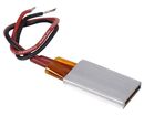
A ceramic heater consists of
- a ceramic plate sandwiched between
- two thin aluminium sheets, to which the wires are soldered.
- an enveloping silicone sheet to provide insulation
- all inserted in a rectangular aluminium tube.
The only sources of supply (at the end of 2019) are the major
online sales platforms in Asia, which sell PTC heaters. They are
intended for uses such as bottle warmers, heating incubators for
chicks, electric hair straighteners, glue guns, perfume sprays, etc.,
with an indicated operating voltage of 12 to 220 volts.
Caractéristiques des ptc retenues pour le cuiseur :36V / 220°C / 35 x 21 mm. Pour une construction à l'unité, l'approvisionnement est une opération... pénible. Characteristics of the ptc selected for the cooker: 36V / 220°C / 35 x 21 mm. If you're building a single unit, procurement is a difficult operation. For purchases of a few dozen units, you can contact hn-yongli.com, which also sells at hn-yongli.en.alibaba.com.
The Achilles heel of these resistors is the invisible soldering between the
wires and the aluminium plates above and below the ceramic. So don't hold
them unnecessarily suspended by the two wires.
A good precaution is to measure the resistance of the ceramics with
an ohmmeter before assembly, to be compared for verification with
identical measurements after assembly of the heating plate. Note that
resistance varies with temperature, especially at low temperatures:
you only need to hold the ceramic in your hand for a short time for the
esistance to vary; nevertheless, it's worth taking measurements before
and after assembly.
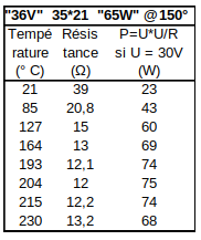
The information provided by suppliers is extremely limited and traceability is non-existent. The only real solution is to test the resistors after purchase on a very simple but amply sufficient test bench: the resistors are powered up and the resistance and temperature are measured to check whether they are suitable for our use. Details of the test bench are provided in the .pdf version of this document. Below: a typical table of readings for a "36 Volt, 220° C, 35 x 21 mm" ceramic powered at 24 Volt. But other choices are of course possible!
Chap 2 Electricity
- 2A) Ohmmeter and Thermometer
- 2B) Electrical wires
- 2C) Line losses
- 2D) The laws of electricity
- 2E) Dangers of electricity
2A) Ohmmeter and thermometer
Ohmmètre
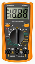
Ohmmeter The multimeter is a versatile device that can be used to
measure electrical voltage and current, among other things, but it is
its use as an ohmmeter that interests us here. The ohmmeter is
used both to measure the resistance of a body and to carry out
continuity tests.
 1) The resistance of a body is its capacity to oppose the passage
of an electric current; it is measured in Ohm (Ω). The ohmmeter
contains an electric battery, which sends out a small electric
current; the user passes this current through the body whose
resistance is to be measured, such as a ceramic. The instrument
reads the resulting voltage drop, and calculates and displays
the resistance in Ω. An ohmmeter generally has several ratings
depending on the size of the resistance; in our case, to measure
the resistance of ceramics, set the selector to the lowest rating,
often "200 Ω"; connect the leads correctly: the black lead to the
"com" terminal (= "common"), and the red lead to the terminal
marked (among others) "Ω". As a guide: a "36 Volt" ceramic
resistor, 35 * 21 mm, has a resistance of around 40 Ohm at room
temperature, and 13 Ohm at 200 °C.
1) The resistance of a body is its capacity to oppose the passage
of an electric current; it is measured in Ohm (Ω). The ohmmeter
contains an electric battery, which sends out a small electric
current; the user passes this current through the body whose
resistance is to be measured, such as a ceramic. The instrument
reads the resulting voltage drop, and calculates and displays
the resistance in Ω. An ohmmeter generally has several ratings
depending on the size of the resistance; in our case, to measure
the resistance of ceramics, set the selector to the lowest rating,
often "200 Ω"; connect the leads correctly: the black lead to the
"com" terminal (= "common"), and the red lead to the terminal
marked (among others) "Ω". As a guide: a "36 Volt" ceramic
resistor, 35 * 21 mm, has a resistance of around 40 Ohm at room
temperature, and 13 Ohm at 200 °C.
2) continuity test: if the leads are connected to the ends of an
electrical circuit, or simply if the two ends of the leads are made
to touch, the ohmmeter displays almost 0 Ohm and emits a "beep".
If the electrical circuit under test is not continuous (cable cut,
terminal disconnected, connection error, etc.), the device will
not beep, and you will have to continue your investigations. The
ohmmeter can be used to detect an incorrect connection if,
by manipulating a switch, the current from the ommeter is sent
n a direction other than that intended; it can also be used to
detect a short circuit: if the ohmmeter emits a beep when the
current should not be flowing, there is a problem...
The ohmmeter is therefore the first tool for carrying out the
essential quality control of an electrical circuit, particularly
the wiring of the hotplate. It can also be used to check that
the connection (not visible) between the wires inside the
ceramic resistor is in good condition. If the ohmmeter does
not have a 'beep' function, which is rare, you need to refer
to the display each time to find out whether there is continuity
or not.
When a digital ohmmeter is not connected, it displays "- - - -"
or "1_______" or "OL" (for "Over load").
The ohmmeter produces its own very low current with the
battery, so it should not be connected to an electrical circuit
that is already powered...
An analogue ohmmeter with a pointer must be tared before use:
when you reach the touch points, the pointer should indicate 0 Ω.
There may be an offset, depending on the state of charge of the
battery; in this case, gently manipulate a knob (a potentiometer)
until the pointer is at the correct position, at the end of the green
dial on the right. Digital ohmmeters usually have an automatic
tare function.
Thermometer
The use of a thermometer is necessary when testing ceramics,
and occasionally to measure the temperature of the hot plate, or
to check the performance of the cooker, but the user has no need
for it in the normal use of the cooker. The model of thermometer
shown here is perfectly suited to our needs; it can easily be
found on the web, by typing its reference "TM-902C" into a
general search engine. It's a thermocouple thermometer;
there's almost exhaustive documentation on the subject at
http://aviatechno.net/thermo/thermo01.php .
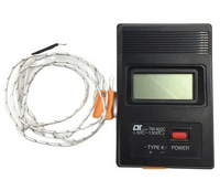 The temperature is measured at the solder joint, the small ball at
the end of the wire. "In a closed circuit made up of two conductors
of different types, a current flows when a temperature difference
is maintained between the two junctions". The thermometer
shown here is a type K thermocouple. The black case contains a
voltmeter. When connecting the thermometer, observe the + and
probes can be purchased, but in principle it is possible to repair
a broken probe by re-soldering the end of the wire, see the
documentation above for reference.
The temperature is measured at the solder joint, the small ball at
the end of the wire. "In a closed circuit made up of two conductors
of different types, a current flows when a temperature difference
is maintained between the two junctions". The thermometer
shown here is a type K thermocouple. The black case contains a
voltmeter. When connecting the thermometer, observe the + and
probes can be purchased, but in principle it is possible to repair
a broken probe by re-soldering the end of the wire, see the
documentation above for reference.
To check the thermometer, dip the probe between a few melting
ice cubes, then into boiling water. There are almost identical
thermometers with two probes, to be consulted alternately;
it may be preferable to have two thermometers, one confirming
the other.
The probe can be immersed in the water in the cooking vessel.
2B) Electrical wires
Fils et cables de puissance.
On the cooker installation, the voltage is not high, below the danger threshold,
but on the other hand the current, also known as intensity or amperage,
s relatively high. Every electrical cable is a resistor (very weak, admittedly,
but it is a resistor) and as such it produces heat by the Joule effect and
therefore produces a voltage drop U proportional to its resistance and
the intensity of the current flowing through it: U = RI. Ohm's law applies
in the same way to electrical cables and resistors. Between the loss of
power and the risk of fire, the question of cable cross-section should
not be taken lightly.
As a rule of thumb, allow a maximum of 6 A per mm² of cross-sectional
area (this is a fairly conservative figure).
Btween a solar panel and the cooker, for two or three metres, use a
2.5 mm² cable; if there are two panels, use a 4 mm² cross-section.
- use only flexible cable to wire the inside of the cooker. A wire cross-section
of 1.5 mm² is suitable; when the ceramics are to be supplied individually,
a cross-section of 0.5 mm² is appropriate.
- use only flexible cable to wire the inside of the cooker. A wire cross-section
of 1.5 mm² is suitable. When the ceramics are to be supplied individually, a
cross-section of 0.5 mm² is appropriate.
H07V-K standard 1.5 mm² single-strand flexible electrical wiring is perfect
for our purposes. The "K" indicates that this is a flexible cable (H07V-U
standard rigid wire is of no use here). But it can be difficult to source,
except in large quantities on the Net. In this case, you can buy a few metres
of "3x2.5mm²" or "3x1.5mm²" flexible cable, easily available in supermarkets
(white cable) and extract the wire you need; it's not very elegant, but
it's simple. For the few metres needed here, you can also use power cables
from old household appliances, provided that the cross-section of the wires
is indicated on the cables. A power cable from a washing machine or
ishwasher provides the wires needed to wire a console; the wires from
a refrigerator power cable have too small a cross-section.
Wires for low currents
For control circuits, very small cross-section wires of the order of 0.1 to
0.3 mm² are more than sufficient; avoid larger cross-section wires, which
would be tedious to install. You can buy them on the internet or... in an
old tower computer or other discarded electronic device.
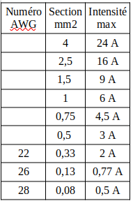
Electrical wire cross-sections are expressed in square millimetres; in English-speaking countries, the old AWG American Wire Gauge system is still in use: "how many wires can fit through a hole of a given diameter? The higher the AWG number, the thinner the wire. Here is a table showing the cross-sections of wires commonly used in Europe.
For low current and electronic wiring, 22 and 26 AWG wires are very suitable.
Wires with Dupont connectors, also known as BJJ connectors, produced
by Adafruit, are 28 AWG (semageek.com ref ADA 1957, or gotronic.fr
ref 12321 etc.)
To connect a "36 V" 35*21 mm ceramic, 22AWG (0.33 mm2) is sufficient;
to connect two ceramics to the same switch: use a 0.5 mm2 cross-section.
2C) Line losses
Numerous pressure loss charts for electrical cables are available on the Internet.
The length to be taken into account when calculating losses is twice the length of a cable:
there is a loss on the outward journey... and the same on the return journey: the voltage
drops when the electricity is used in the resistor, but the current flowing back to the
transducer-generator is equal to that which left it, and the line loss is a function of the
current (also known as the amperage) and not the voltage.
2D) The laws of electricity
An electrical dipole is an electrical component with two terminals: lamp, switch,
battery, resistor, motor, etc.
- The voltage difference across an electrical dipole, also known as "voltage drop" ,
or simply "voltage", is denoted U and measured in Volt (V).
- The quantity of electric current passing through a dipole, called "Intensity", +
also known as "current" or "amperage", is noted I and measured in Amperes (A).
- The resistance of a body or dipole is its capacity to oppose the passage of an
electric current; it is noted R, and measured in Ohm (Ω).
For a given resistance value, a dipole will allow more current to pass through it
the greater the voltage difference applied to its two terminals: I = U/R is Ohm's
law, also known as U = RI.
A dipole - for example a ceramic - through which an electric current flows
produces heat, the Joule effect. The higher the voltage and current, the more
heat is released: P = UI
So we have a system with two equations: U = RI and P = UI
In the first equation, replace I by U/R; P = U(U/R); therefore P = U²/R,
Similarly, in the second equation, replace U with RI: P = (RI)*I; therefore P = RI².
Combining resistors
- When resistors are connected in series, the R values of their resistances
add up, creating successive bottlenecks.
- when resistors are connected in parallel, the current has several points of passage
at the same time; then, the inverses of the resistances are summed.
2E) The dangers of electricity
On the subject of dangerous levels of electricity, see for example
technipass.com .
And here is an article on low voltage
Given the electrical resistance of the human body, and if the direct current voltage
is less than 48 volts, then the quantity of electricity capable of passing through
the human body is below the danger threshold: Ohm's law applies to the human
body as it does to other bodies. Example of application: on a public works site,
the site current is distributed at 380 volts alternating current. But to power a
concrete vibrator, operated by an operator perched on top of scaffolding, the
current is first converted to 42 V DC.
In the case of our cooker, which operates wisely at around 30 V at cruising
speed, with a peak at 38 V, and which has no battery, the potential risk due
to electricity is to be considered zero compared with that of a wood fire.
The major risk is that of heat energy stored in the boiling cooking vessel -
but this is, by definition, a risk inherent in any cooking operation.
On the other hand, when energy is stored, even in the form of a 12-volt battery,
there is a risk and a danger: on this point, see Part 8, Chapter 4.