
PHOTOVOLTAIC SOLAR COOKING
WITHOUT BATTERIES
WITH PTC CERAMIC HEATERS

General summary of the documentation:
- Home
- Presentation of the cooker
- Design of the cooker
- 1 - Building and using a cooker
- 2 - Building a cooker: appendices
- 3 - Theoretical presentations
- 4 - Technical information
- 5 - Photovoltaic panel supports
- 6 - Automation of PTC ceramics
- 7 - Photovoltaic solar water heater
- 8 - Library
- Who are we?
the parts shown in grey are still under construction.
Part 1 CONSTRUCTION AND USE OF A COOKER

- Chap 1 The cooker base
- Chap 2 The control panel
- Chap 3 The heating block
- Chap 4 Installing and using the cooker

The cooker proposed here is designed to work with a photovoltaic panel of
around 350 Watt-peak, 40 Volt maximum / 10 Amp maximum.
Construction is in three main stages, designed to facilitate self-build by a careful
amateur, and therefore also by a craftsman or technician. Part 2, "Appendices",
provides further details.
The cooker can be built in a multitude of variants, the model shown here can be
adapted to suit individual needs and possibilities.
Note you can click on the diagrams and enlarge them.
Chapter 1 The base of the cooker
- Cut the 533 x 335 mm base plate from 8 mm thick plywood, "exterior" quality if possible. Fit battens with a 10 mm margin around the edge.

- Make the top plate of the base;
fit a small batten.

- Assemble the base

Control panel supports
prepare the two short sides ,

prépare the rear and front faces ,

and assemble the control panel supports on the base.

Chapter 2 The control panel
The control panel is equipped with
- a main switch (optional)
- individual switches to power each PTC ceramic resistor separately. The user
operates the switches until the maximum amount of energy is obtained from
the photovoltaic panel, taking into account the current level of sunlight.
- a wattmeter which allows the user to confirm their choice.The wattmeter
is to the user what a compass is to a sailor.

If the panel is made of plywood, it is advisable to add supports made of thinner
material (sheet metal, PVC sheet, etc.) to be able to fit the components: switches
and Wattmeter, and this is the solution chosen here.
The dimensions of the openings and supports need to be confirmed during construction.
Below: Control panel, in 8 mm plywood.

Cut out the thin component support plates, in sheet metal, 3 mm thick PVC, etc.

Install the components and screw the thin plates to the console

Wiring the console
Turn the plate over and install it on two cleats for easier working.
Use only H07V-K standard flexible wire, see part 5 for more details.
Start wiring with the earth cable, in blue or black. The connection to the
inlet from the sensor can be made using a domino, for example, which
should be fixed firmly to the side of the cooker to prevent any inadvertent
force being applied to the switch.
If necessary, refer to the second part "Appendix" for installation details.
N.B. all diagrams can be enlarged.

Wiring of the power supply wire, first phase.

Wiring of the supply wire, second phase.
The wires are split in order to protect the internal contacts of the switches
(DC flash effect, and compliance with the manufacturer's specifications).

Protecting the Wattmeter screen
The screen should be protected from the heat of the sun, for example with
a small piece of leather or similar, fixed with copper wire or screws. A
light-coloured protection would be preferable.

install the console on the base of the cooker, passing the cables through the double bottom.

Chapter 3 The heating block
Now we come to the heart of the cooker, the part that makes it so new and original. Follow the instructions step by step, consulting the additional information in part 2 "Appendix" as necessary, and you will be successful in the end.
- 3A) The heating plate
- 3B) PTC ceramic resistors
- 3C) Making a cork plate and a support plate for the heating block
- 3D) Assembling the heating block
- 3E) Wiring the heating block
- 3F) The insulation extension

Round plate,diameter 142 mm, thickness 5 mm, cut out of ordinary
aluminium sheet by any means (jigsaw, or to be cut out by water jet, laser....). The
plate must be perfectly flat and must not have been hammered.
- Four holes with a diameter of 6.2 mm (or 6 mm if this is not possible) for the
plate supports around the perimeter.
- 4.2 mm diameter holes (or 4 mm if not available) for fixing the ceramic
heating elements


In the Part 2'appendices' you will find  - the drilling plan, to be printed and attached to the aluminium plate, so that you
don't have to draw any lines. To start the holes, use a centring drill bit.
Do not use a punch...
- the drilling plan, to be printed and attached to the aluminium plate, so that you
don't have to draw any lines. To start the holes, use a centring drill bit.
Do not use a punch...
- a drawing in DXF format for use on a numerically controlled machine.

Countersink should be carried out using a 90° angle countersink bit. It is essential to check that the screw heads are correctly embedded in the sheet metal. At the end of the operation, deburr all countersinks with abrasive cloth (180 grit or more). A correct heating plate guarantees good heat transfer to the cooking vessel.

Ceramic resistors are at the heart of the cooker's operation.
We use 35 x 21 mm "36 Volt" ceramic resistors, 5 mm thick. For their supply,
see Part 4 "Technical Informations". Before installing the ceramics, the ends of the
wires should be tinned with a soldering iron.
The ceramics are held in place by M4 countersunk screws, length 16 mm.
To ensure good heat transfer, they must remain in close contact with the
aluminium plate. It is therefore essential to use Belleville spring washers.
See the Wikipedia article on Belleville washers.
In ceramic resistors, the most fragile part is the (invisible) soldering of
the wires to the small aluminium plates inside the silicone insulator.
Ceramics should not be handled carelessly, particularly by holding
them by the wires, to avoid weakening or even destroying the soldering.
A check with an Ohmmeter is a wise precaution. On the use of the
Ohmmeter, see Part 5, Chapter I . For all intents and purposes:
the resistance of a ceramic such as those used here is of the order
of 40 Ω at 21°C, but it varies very quickly with temperature; if
necessary, see Part 6. Make sure the surfaces are clean before
assembly.
In front of each screw, it is necessary to make a notch with a file
on the side of the ceramics, which will thus be held in all directions.
Once the notch has been made ... carefully remove the burrs
left by the file.
Turn the hot plate over and install the ceramic heaters on the
underside. Assemble the ceramic wires in pairs, for example
with a small bracelet cut from heat-shrink tubing.

The usefulness of the cork plate has not really been established. It is installed as a precaution. Thickness: approximately 10 mm

Cut the support plate for the heating block from 8 mm thick plywood. Draw a circle 142 mm in diameter to indicate the maximum space required for the connection terminals between the heating unit and the console.

The heating block is assembled using four M 6 flat-head screws, length = 80 mm . Install and bolt the screws to the heating plate, making sure to insert a lock washer for each screw to prevent them from loosening. Tighten the nuts firmly and permanently. The lock washers must be completely flattened.

Install a nut and a flat washer on each screw, so as to leave a 30 mm gap between the underside of the heating plate and the cork disc.

Position the cork disc. Take care when handling the wires. Install a washer and nut on each M6 screw, and tighten moderately on the cork disc. Fit another nut and washer on each screw, to receive the heating block support plate. On the same screw, the two nuts touch back to back, and can even be locked together.

Install the heating block support plate. Secure the plate with washers and nuts. Insert a fan washer (or lock washer) between the washer and the nut, to reduce the risk of loosening.

Install two strips of six dominoes, taking care to stay within the
142 mm circle (which will later correspond to the cut-out in the top plate
of the base). Comb the wires, grouping them into 4 groups of twice two wires.
Do you need to identify the eight ceramics and assign them to the eight
switches by name? this would be of no major use.

For each group of four wires
- the two earth wires are connected to the ends of the bars.
- the two power supply wires each have their own domino.
Once the dominoes have been wired, it would be wise to carry out a small
inspection using an Ohmmeter. One point on a ground domino, the other
on one of the two power supply dominoes, and you should hear "beeeep"...
If ever some wires are too short, it's not a big deal, you can always connect
a short length of wire, solder, and protect the connection with one or
two layers of heat-shrink tubing.

Place the heating block, still upside down on the base of the cooker, and start wiring the control panel with the dominoes.

NOTE : each power wire from the control panel is connected to a single PTC, while each ground wire from the control panel is connected to two PTCs.
Wiring is done

Turn the heating block over , insert the wires in the double base and install the heating block on the base of the cooker, securing it with 4 small screws.


Chapter 4 The cooker: Installation, Use, Performances
- 4A) Installing the cooker
- 4B) Using the cooker
- 4C) Measuring the performance of the cooker
4A) Installing the cooker
The cooker can be installed anywhere the user wishes, inside or
outside a building, on one condition: it must be as close as possible
to the photovoltaic panel, so as not to dissipate energy in the
electrical cable. Given the characteristics of the electrical current
supplied by the panel, this is an inescapable problem. For ONE
300 Watt panel only:
- Cable up to 3 metres long: use a cable with a cross-section of 2.5 mm².
- Maximum cable length 6 metres: use a cable with a cross-section
of 4 mm².
If the cooker is outdoors, protect the small Wattmeter screen
from direct sunlight.
To connect the cooker and the sensor, you can use Ø 4 mm
banana plugs, for example: conrad.fr ref 1582242 .
4B) Using the cooker
Choosing the cooking pot
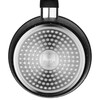
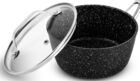
Its first quality must be a flat base; a container with a convex base
will not work.. Its second quality is that it should not be too large: in the case of a large saucepan only half full, the top half of the saucepan is only used to cool the bottom half.
For a 375 Watt-peak panel, an 18 cm diameter aluminium saucepan with an electric base is perfectly suitable, and of course with a lid, glass if possible. The tail of the pan is a big hindrance to insulation, so it's best to dismantle it or cut it off.
Why not use a pressure cooker? A pressure cooker of up to 3.5 litres seems a reasonable size; smaller ones are also available, from 1.5 litres upwards. In the case of two cookers working alternately in "Norwegian kettles", the Norwegian kettle effect would start at 110° C (or 120° depending on the model), instead of starting at 100° C with ordinary containers.
Insulation
This is the condition without which there is no point in operating
the cooker. Small cotton terry towels are the best choice, to be
dried between each use and washed regularly. There is no risk
of them catching fire, as the temperature of the electric resistors
does not allow this; however, a small wire mesh such as chicken
wire or larder wire around the heating block would be welcome.
The condition of the hotplate surface.
The hotplate must be clean, as any dirt will prevent the heat
from passing through. The bottom of the container must
also be clean. Before placing the container on the hotplate,
check that there are no grains of sand or anything else.
A thin layer of air between the plate and the bottom of the
container acts as an insulator. A few grains of sand are
enough to prevent the cooker from operating.
If you have any doubts about the flatness of the hot plate
or the container, pour a spoonful of oil onto the plate, place
the container on it and turn it around a little, then observe
the distribution of the oil on the bottom.
Types of cooking.
When cooking, there are two phases: heating the food and
then the actual cooking, which requires much less heat,
since all that is needed is to compensate for the losses to
maintain the temperature. Since the container is insulated,
the cooker is comfortable during the second phase, but as
it is not very powerful, the heating period is longer than
with other cooking methods (at the cost of a much higher
energy consumption, but that's another problem).
But we know that water is the most difficult body to heat.
It is therefore when cooking with water (tubers, pasta, etc.)
that the cooker will be the least efficient. When cooking pasta,
you need to uncover the lid, which wastes a lot of heat,
and when cooking couscous, the usual couscoussiers are
too big for a small cooker like the one proposed here.
This type of cooking should be reserved for traditional
methods.
For cooking rice, the cooker is more efficient for cooking
pilaf rice (one and a half to two times its weight in water)
than for cooking rice in water (which requires 5 measures
of water for one measure of rice).
Pending the availability of larger cookers - which is entirely
feasible - the cooking methods of choice are those in which
the food cooks in its own water, without the addition of
liquid (this is one of the definitions of braising). It is
possible to combine foods that produce a lot of juice
(tomatoes, courgettes, etc.) with those that do not
produce any at all (potatoes, carrots), the latter being
cut into small pieces. In the end, all of the above are
just common sense.
Operating the cooker.
On the control panel, the driver has a three-position button
on his left: position 0, where nothing happens, position I to
start the cooker, and position II to use the solar panel for
other purposes (recharging mobile phones or USB solar
lamps) when the cooker is not in use.
The driver switches on the heating elements using the buttons
on his right, each of which controls a heating element. It's
up to the driver to find the best combination, given the
amount of sunshine. To help him make his choice, the
driver has an electrical measuring device on which
to read the power in Watts.
Sunlight is constantly changing, and so is the power it
delivers. There's no point trying to keep track of it minute
by minute. Once you've made the right choice, you don't
have to go back to your cooker unless there are
significant variations in sunlight. He can go about his
business, as the food is very unlikely to stick to the
bottom of the container.
An original scenario
The ceramic electrical resistors installed under the hotplate
behave differently to conventional electrical resistors. They
regulate themselves, and do not exceed 200°. Once they reach
this temperature, they consume very little electricity - just
enough to keep them stagnant. You can try this out: in very
fine weather, run the cooker without a container, and it will
consume all the electricity available to raise the temperature
of the hot plate. Once the temperature reaches 200°C, the
wattmeter will drop significantly while the sun continues to
shine, making you wonder whether the sensor is
malfunctioning. If you then place an empty container on the
plate, consumption increases rapidly, then starts to stagnate
again; and by adding one or two glasses of water to the
container, everything returns to normal.
Reminder of instructions for the user
To follow the sun in its east-west path, the sensor should only
be dragged along the ground by pulling the base using a cord
or a hook made, for example, of Ø 8 mm concrete reinforcing bar.
It is strictly forbidden to push or pull on the mobile cradle, and
therefore to deform it, as this could crack the glass surface.
4C) Measuring the cooker's performance
There is a simple method for measuring the performance of the
cooker: place a litre of cold water in a container and measure
the time taken to bring the water to the boil. The measurement
should be carried out in good conditions, but not necessarily
in perfect conditions
- sunshine of the order of 900 W, well established sunny weather,
with clear shadows on the ground.
- photovoltaic panel correctly oriented
- insulation correctly installed
- use of a thermometer, see part 4.
The question arises as to the precise definition of the boiling
point: is it a simmering, strong or violent boil? Between one and
the other, the time lapse can be longer than a few minutes,
which biases the measurement. The best solution is to stick
to a temperature rise to 97 or 98°C, and to state the result as
follows, for example: "to raise one litre of water from a
temperature of 17°C to 97°C, XX minutes were needed".
Some basic thermal calculations
By definition, the Joule is the unit of measurement for
energy, whether thermal, electrical, mechanical, etc.
Water is the most difficult body to heat: 4.18 Joules
are needed to raise the temperature of 1 gram of
water by 1°C. This is the definition of the heat of
mass of water.
So raising the temperature of one kilogram of water from
17 to 97°C is equivalent to doing 1,000 grams of work
* (97-17°C) * 4.18 Joule = 334,400 Joule (excluding heat losses...).
By convention, when a thermal, electrical or mechanical
machine produces work of 1 Joule per second, it is said
to have a power of 1 Watt.
In our case, a temperature rise in 35 minutes. 35 *60 = 2,100 seconds.
Since the work of 334,400 Joules was carried out in 2,100 seconds,
the useful heating power was 334,400/2,100 ≈ 160 Watt.
Let's not rush to draw any major qualitative conclusions from
these figures, until we have other elements of comparison...
And it's always possible to add photovoltaic collectors....
The 160 watts seem very low compared with the 1200 watts
of a gas cooker burner. But the 160 watts represent the work
done, whereas the 1,200 watts represent what we pay the energy
supplier, regardless of how we use it and all the heat that passes
around the pan.
These are figures where everyone can see noon at their own door,
and which can fuel discussions well into the evening. When all
is said and done, one wonders whether the 1200 W of a gas
cooker fire, with a flame at 1800°C, is not pure waste when it
comes to heating a pan of food to 100°C....
Measuring the cooling time provides a good indication of the
quality of the insulation; the order of magnitude is a drop from
100 to 90°C during the first half hour after heating stops.
We can thus -and this is very interesting!- calculate the
power of the losses.